
Earthing Strip Installation
Table of Contents
- 1..Introduction to Earthing Strip Installation
- 2..What is an Earthing Strip?
- 3..Types of Earthing Strips
- 4..Earthing Strip Size and Specifications
- 5..Materials Required for Earthing Strip Installation
- 6..Earthing Strip Installation Process
- 7..Underground Earthing Strip Installation
- 8..Vertical Earthing Strip Installation
- 9..Earthing Strip Jointing and Connection
- 10..Connection with Earthing Electrode
- 11..Earthing Strip Testing
- 12..Advantages of Earthing Strip Installation
- 13..Applications of Earthing Strips
- 14..Safety Precautions
- 15..Frequently Asked Questions
Introduction to Earthing Strip Installation
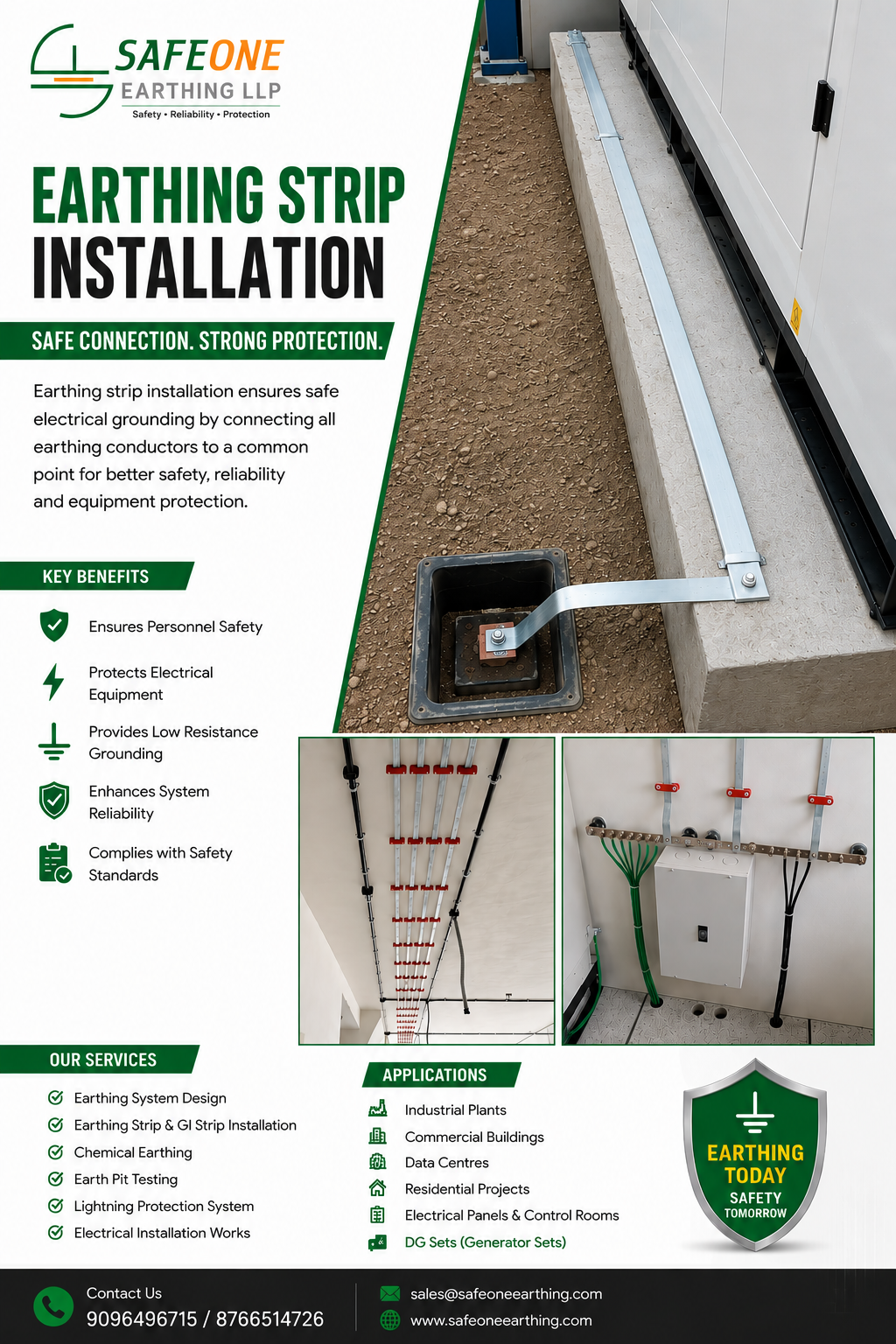
Earthing strip installation is an important part of an electrical grounding system. An earthing strip provides a low-impedance conductive path between electrical equipment, structures, earth electrodes, earth pits, and the grounding network. It helps safely carry fault, leakage, and transient currents toward the earth, reducing the risk of electric shock, equipment damage, and electrical hazards.
GI (Galvanized Iron) and copper strips are commonly used depending on the project requirements, environmental conditions, electrical design, and applicable standards. Proper sizing, routing, jointing, and testing are essential for achieving a reliable and long-lasting earthing system.
At Safeone Earthing LLP, we provide professional earthing strip installation services using GI (Galvanized Iron) and Copper Earthing Strips for industrial, commercial, residential, and infrastructure projects. We provide GI strip supply, installation, jointing, routing, connection, and testing as part of complete earthing solutions. Our GI earthing systems are suitable for electrical panels, transformers, DG sets, machinery, substations, buildings,
What is an Earthing Strip?
An earthing strip is a flat metallic conductor used to connect electrical installations and equipment to an earthing system. Unlike a conventional round earthing wire, a strip provides a broad conductive surface and can offer good mechanical strength for industrial and commercial installations.
GI earthing strips are widely used because they provide good mechanical strength and corrosion protection through galvanization. Copper strips are also used where higher electrical conductivity and specific corrosion-performance requirements are required.
The earthing strip is normally connected between an earth electrode or earth pit and the equipment, electrical panel, transformer, structure, or main earthing bar.
Types of Earthing Strips
The most commonly used earthing strips include:
GI Earthing Strip
Galvanized Iron strips are widely used for industrial, commercial, residential, infrastructure, and electrical installations. The zinc coating helps protect the steel against corrosion.
Copper Earthing Strip
Copper has high electrical conductivity and excellent corrosion resistance in many environments. Copper strips are commonly selected for applications where conductivity and material compatibility are important.
Stainless Steel Earthing Strip
Stainless steel strips can be considered for specialized installations where higher corrosion resistance is required, particularly in aggressive or chemically exposed environments.
The appropriate material should be selected according to the earthing design, environmental conditions, connection materials, fault-current requirements, and applicable standards.
GI Earthing Strip
Galvanized Iron strips are widely used for industrial, commercial, residential, infrastructure, and electrical installations. The zinc coating helps protect the steel against corrosion.
Copper Earthing Strip
Copper has high electrical conductivity and excellent corrosion resistance in many environments. Copper strips are commonly selected for applications where conductivity and material compatibility are important.
Stainless Steel Earthing Strip
Stainless steel strips can be considered for specialized installations where higher corrosion resistance is required, particularly in aggressive or chemically exposed environments.
The appropriate material should be selected according to the earthing design, environmental conditions, connection materials, fault-current requirements, and applicable standards.
Earthing Strip Size and Specifications
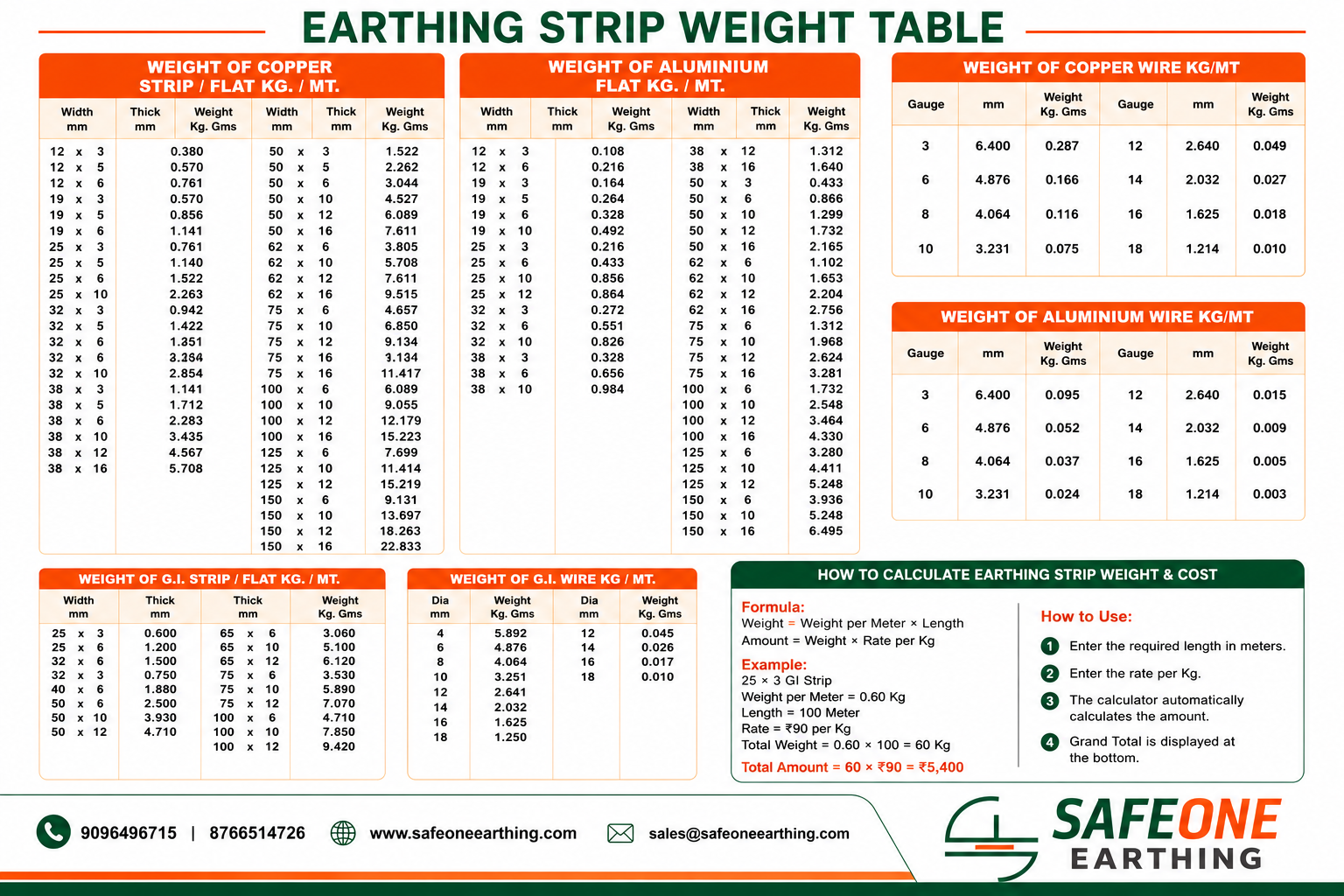
Earthing strip size should not be selected only on the basis of convenience. It should be determined according to the electrical design, fault-current requirements, installation conditions, mechanical requirements, and applicable standards.
Common GI strip sizes used in different installations include:
- 25 × 3 mm GI Earthing Strip
- 25 × 6 mm GI Earthing Strip
- 32 × 6 mm GI Earthing Strip
- 40 × 6 mm GI Earthing Strip
- 50 × 6 mm GI Earthing Strip
- 50 × 10 mm GI Earthing Strip
- 50 × 12 mm GI Earthing Strip
Copper strips are also available in various widths and thicknesses depending on the project requirements.
The correct size should always be determined by a qualified electrical designer or engineer rather than selecting a strip solely based on commonly available sizes.
Materials Required for Earthing Strip Installation
The materials required depend on the type and configuration of the earthing system. Typical materials include:
- GI or copper earthing strip
- Earthing electrode
- Earth pit or inspection chamber
- Suitable clamps and connectors
- Bolts, nuts, and washers
- Welding or approved jointing materials where specified
- Corrosion-protection material
- Cable/strip supports and clamps
- Identification labels
- Backfill or earthing enhancement material where required
- Test links or disconnecting arrangements where required
All components should be compatible with the earthing system and suitable for the installation environment.
Earthing Strip Installation Process
A typical earthing strip installation involves the following steps:
1. Site Survey
The installation area is inspected to identify electrical equipment, earth pits, cable routes, structures, and the proposed grounding network.
2. Earthing Design
The required earthing points, conductor sizes, electrode locations, connection arrangements, and routing are determined according to the project requirements.
3. Material Selection
The appropriate GI, copper, or other approved earthing conductor is selected according to the design.
4. Route Preparation
The route for the earthing strip is prepared. Underground routes may require trenching, while above-ground installations require suitable supports and protection.
5. Strip Installation
The earthing strip is installed along the approved route and connected to the earth electrode, earth pit, equipment, panel, structure, or earthing bar.
6. Jointing
Where multiple strips need to be connected, suitable approved joints or connection methods are used to maintain electrical continuity.
7. Inspection and Testing
The completed system is inspected for mechanical integrity, continuity, connection quality, and earth resistance before commissioning.
Underground Earthing Strip Installation
Underground earthing strips are commonly installed to connect earth pits and electrodes with electrical panels, transformers, machinery, buildings, and other grounding points.
A suitable trench is prepared according to the project design. The strip is routed through the trench and protected from mechanical damage and environmental exposure as required.
The route should be planned to minimize unnecessary bends and joints. Connections should be properly secured and protected against corrosion. After installation, the trench can be backfilled according to the approved installation specification.
Proper underground installation helps protect the conductor from accidental damage while maintaining a reliable connection between different parts of the grounding system.
Vertical Earthing Strip Installation
Vertical earthing strip installation is used where the grounding conductor needs to be routed vertically along a building, structure, electrical shaft, equipment support, or other suitable route.
The strip should be securely supported using appropriate clamps or brackets. Adequate mechanical protection should be provided where the conductor is exposed to impact, movement, or other physical hazards.
The vertical route should be planned to provide a continuous and reliable grounding connection while maintaining accessibility for inspection and maintenance where required.
Earthing Strip Jointing and Connection
Proper jointing is one of the most important aspects of earthing strip installation. A poor connection can increase resistance and compromise the reliability of the grounding system.
Depending on the design and materials, earthing strips may be connected using suitable bolted connections, approved clamps, or other specified jointing methods.
Connections should be:
- Mechanically secure
- Electrically continuous
- Properly aligned
- Protected against corrosion
- Accessible for inspection where required
When dissimilar metals are connected, appropriate measures should be taken to reduce the risk of galvanic corrosion and ensure long-term reliability.
Connection with Earthing Electrode
The earthing strip connects the electrical installation to the earth electrode through the grounding network. The electrode provides the interface between the grounding conductor and the surrounding soil.
The connection should be mechanically strong and electrically continuous. Depending on the earthing design, suitable clamps, connectors, or other approved connection arrangements may be used.
The connection point should be protected against corrosion and accidental mechanical damage. The overall earthing system should then be tested to verify its performance.
Earthing Strip Testing
Testing is essential after earthing strip installation. It helps verify that the grounding system has adequate electrical continuity and earth resistance for its intended application.
Earth resistance can be measured using an appropriate earth resistance tester and a suitable testing method. Depending on the installation, continuity and bonding connections may also be checked.
Testing should be carried out by qualified personnel using properly calibrated test equipment. Test results should be documented for future inspection, maintenance, and comparison.
Regular testing is also recommended as part of an electrical maintenance program, particularly for industrial facilities, commercial buildings, substations, transformers, and other critical installations.
Advantages of Earthing Strip Installation
Properly installed earthing strips provide several benefits:
- Provides a reliable grounding path
- Helps dissipate fault and leakage currents into the earth
- Supports electrical safety
- Helps protect electrical equipment
- Provides electrical bonding between equipment and structures
- Offers good mechanical strength
- GI strips provide corrosion protection through galvanization
- Suitable for industrial and commercial grounding networks
- Can be routed between multiple earthing points
- Supports the overall reliability of the electrical installation
The actual performance of an earthing system depends on the complete grounding design, conductor sizing, electrode arrangement, soil conditions, connections, and maintenance.
Applications of Earthing Strips
Earthing strips are used in a wide range of electrical and industrial applications, including:
- Industrial plants
- Commercial buildings
- Residential buildings
- Electrical substations
- Transformers
- Distribution panels
- Control panels
- DG generator installations
- Solar power systems
- Manufacturing facilities
- Data centers
- Machinery and equipment
- Cable and electrical infrastructure
- Lightning protection systems
- Electrical equipment bonding
- Telecommunication installations
The type and size of earthing strip should be selected according to the specific requirements of each installation.
Safety Precautions
Earthing strip installation should be performed by trained electrical personnel following the approved electrical design and applicable safety requirements.
Important precautions include:
- Use the correct conductor size: Select the earthing strip according to the electrical design and applicable requirements.
- Ensure proper connections: Loose or poorly made connections can increase resistance and reduce system reliability.
- Protect against corrosion: Connections and exposed sections should receive appropriate corrosion protection.
- Provide mechanical protection: Protect strips from impact, physical damage, and unauthorized interference.
- Avoid unnecessary joints: A continuous conductor route is generally preferable where practical.
- Check electrical continuity: Verify that the complete grounding path is electrically continuous.
- Test the completed system: Earth resistance and other required tests should be performed using appropriate instruments.
- Maintain records: Keep test results and installation documentation for future maintenance.
- Follow the approved design: Do not change conductor size, route, or connection arrangements without appropriate technical review.
- Work safely: Electrical work should be carried out only after appropriate isolation and safety procedures have been followed.
Frequently Asked Questions
Earthing strip installation is the process of installing a conductive metal strip, such as GI or copper, to connect electrical equipment and structures with an earthing electrode or grounding network.
GI and copper are commonly used. The appropriate material depends on conductivity requirements, corrosion conditions, mechanical requirements, environmental exposure, and the overall earthing design.
Common sizes include 25 × 3 mm, 25 × 6 mm, 32 × 6 mm, 40 × 6 mm, and 50 × 6 mm. The required size should be determined according to the electrical design rather than simply selecting a standard size.
Yes. Copper strips can be used where their high conductivity, corrosion performance, and compatibility with the grounding system make them suitable.
The strip is connected to the earth electrode using an appropriate approved connection method. The connection should be mechanically secure, electrically continuous, and adequately protected against corrosion..
Yes. Underground installation is commonly used to connect earth pits and electrodes with electrical panels, transformers, buildings, machinery, and other grounding points.
Earthing strips can be joined using suitable approved mechanical or connection methods depending on the conductor material and project specifications. The completed joint should provide reliable electrical continuity.
Testing helps verify the continuity and earth resistance of the grounding system. It can identify poor connections or other issues that may affect the performance of the earthing installation.
GI strips are steel strips protected with a zinc coating and are widely used because of their mechanical strength and corrosion protection. Copper strips have higher electrical conductivity and are selected for applications where their electrical and corrosion characteristics are advantageous.
Earthing strips are used in industrial plants, commercial buildings, substations, transformers, electrical panels, generators, solar installations, machinery, data centers, and other electrical grounding systems.
The conductor size affects the conductor's ability to safely carry fault current and its electrical characteristics, but the overall earth resistance is also strongly influenced by the electrode arrangement, soil resistivity, grounding network, connections, and installation conditions.
Testing frequency depends on the type of installation, operating environment, applicable requirements, and maintenance program. Industrial and critical electrical installations may require periodic inspection and testing.
Earthing strip installation should be carried out by qualified electrical professionals who understand grounding design, electrical safety, installation practices, and applicable standards.